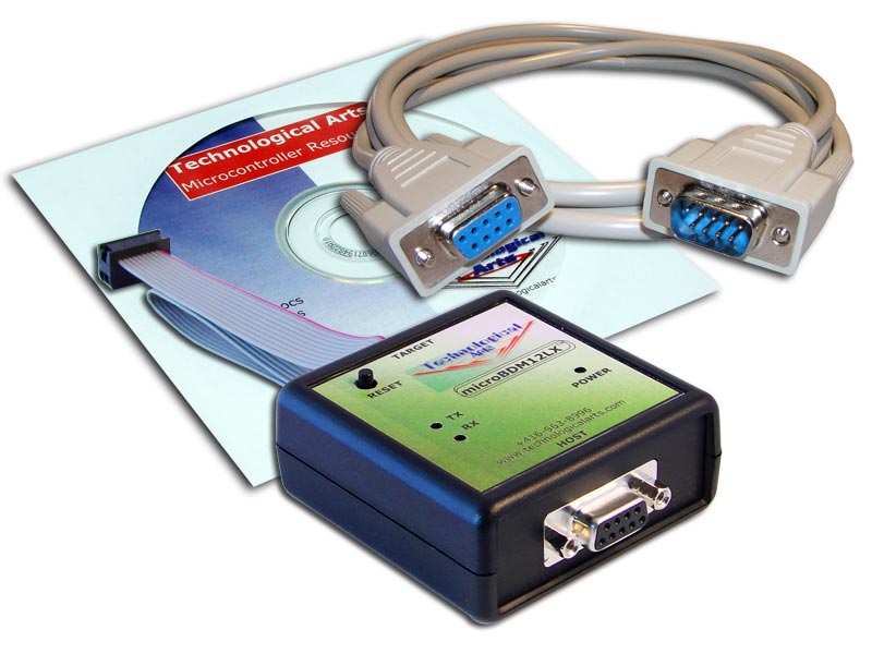
This tutorial will assume you are using a MicroBDM12LX pod from Technological Arts
(http://www.technologicalarts.ca/shop/store/details/553/40/microcontrollers/9s12/debugging-tools/bdm-pod-for-9s12-targets,-rs232-interface.html)
Download this file: db12DP256-16.S19 from
http://support.technologicalarts.ca/docs/Adapt9S12DP/Code/D-Bug12/db12DP512-16.S19
Refer to the component layout diagram for Adapt9S12DP256 here:
http://support.technologicalarts.ca/docs/Adapt9S12DP/ad9s12dp256pins1.pdf
Plug the BDM pod's ribbon cable into the BDM In connector (J5) on the board.
Connect the supplied serial extension cable between the BDM pod and an available ComPort on your PC.
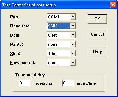
Launch any terminal program (we'll use TeraTermPro here), and select the ComPort you have the BDM pod attached to.
Adjust the terminal program settings for the chosen ComPort to:
baud=96008
data bits
No Parity
1 Stop bit
Xon/XOFF (i.e software handshaking)
Apply power to your board, and you'll see the Green power LED activate on the BDM pod.
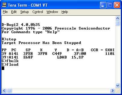
The BDM pod's D-Bug12 prompt will appear in the terminal window.
If you get a message saying D-Bug12 is unable to communicate with the target board, enter 2 to Reset Target
If the message persists, check the Target Speed shown, and correct it if necessary.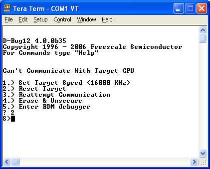
Once you see an S prompt, you are ready to proceed.
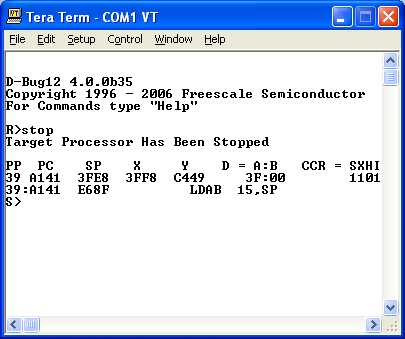
If you see an R> prompt instead, enter stop to halt your target board's CPU.
Type the following commands:
fbulk
fload
Now use the terminal program's Send ASCII (or Text) File to send the D-Bug12 file to your board.
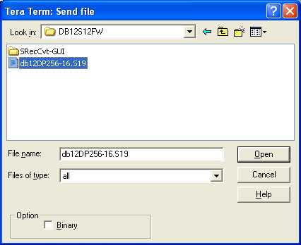
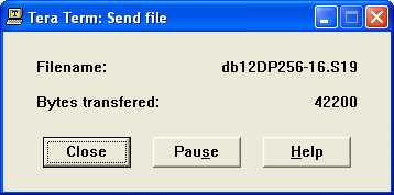
Click Open, and the File transfer will begin.
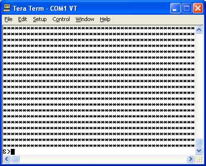
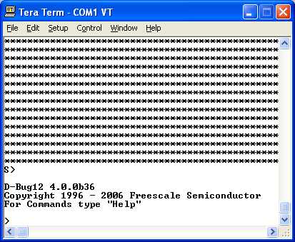
You'll see a number of asterisk characters (*) displayed in the terminal window as the file is programmed, and the S> prompt will be displayed when it has finished.
Remove the BDM pod.
Plug the serial cable into your Adapt9S12DP256 board.
Ensure that the jumpers on the board are set as follows:
JB1: MODA=MODB=0 (i.e. run MCU in SingleChip Mode)
JB3: PAD00=PAD01=0 (i.e. D-Bug12 Mode = EVB)
JB4: remove (i.e. place on one pin only)
Press the reset button on your board, and you should see the D-Bug12 sign-on prompt in your terminal window.
You're done!